|
ASkr 8/2009:
PAGE REDESIGN IN PROGRESS...
I just received a Fischertechnik Robo-TX.
Equipped with:
(You will find all this in the Robo-TX firmware file ;)
8MB RAM and especially 2MB flash are somehow ridiculous and unfortunately not enough for Linux.
After having my experience with Linux on a Linksys WRT54G
router, I can tell you that this is no fun at all... Therefore, the Robo-TX is subject of getting lualized ;-) Digital/analog IOs should be a piece of cake, PWMs and interfaces (I2C/UARTs/...) not too challenging but somehow I doubt that the bluetooth part can be operated.
We will see..
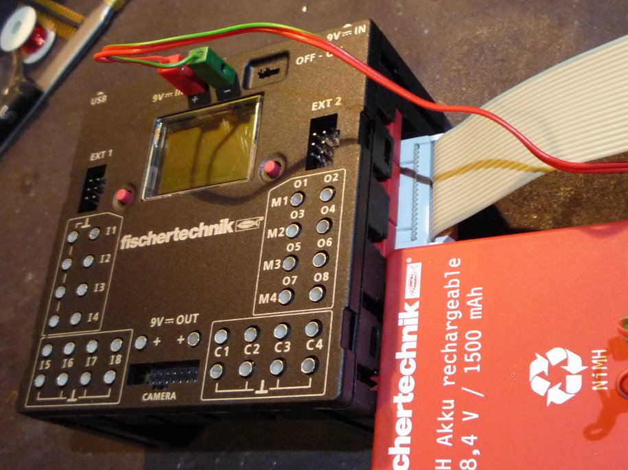
It looked much bigger in the WWW. I did not expect a flatfish... 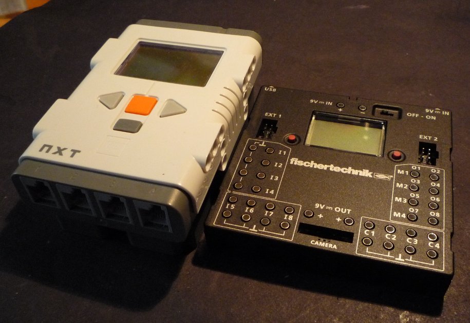 A closer view. 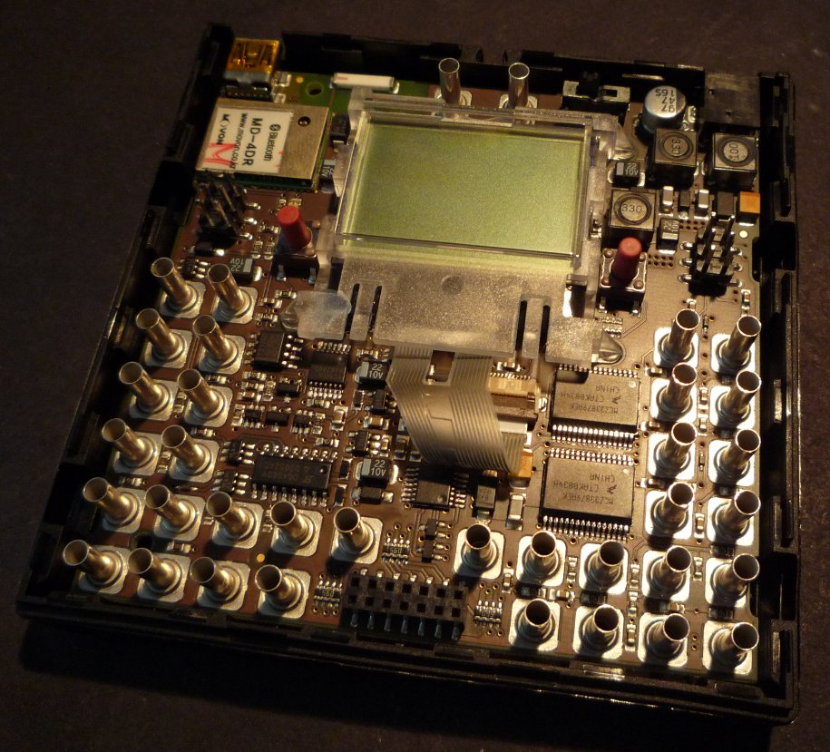 The parts of interest... 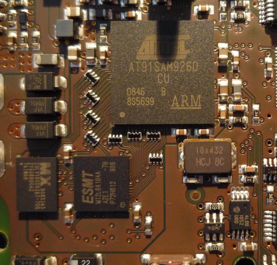 Powered up normally, it has VID:PID 146A:1000 (*1*) Holding down the left, red button while powering up results in having a SAM-BA compatible USB connection ;-) 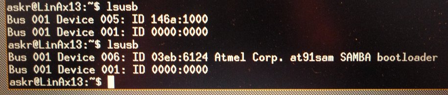 (*1*)
Assuming you are running linux: modprobe usbserial vendor=0x03eb product=0x6124
Type "dmesg" to see the device your Robo-TX now is attached too (usually "/dev/ttyUSBx")
Assuming you are running windoze: If powered up normally, you will see the "Fish-Term", FTs serial terminal. Beside the commands that are listed via "?", there are some more:
Especially "erase_boot" sounds scary. But I _assume_ (!assume!) this command refers to a RoboPro downloaded and automatically executed byte code? I really can not believe they are referring to the flash memory boot loader... I suggest you better keep your hands off scary commands ;)
Right now, we're working on a little FT Robo-TX bootstrap file.
mhhh... 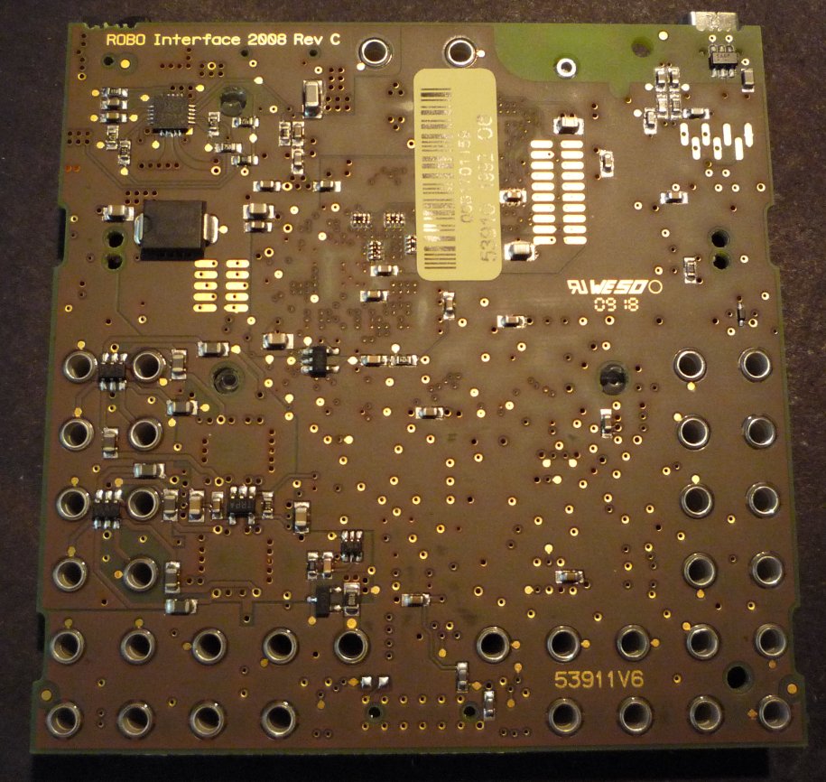 Randnotiz: Alles aus deutscher Hand, HW, SW und PCB. So würde ich mir das von vielen wünschen...
what? 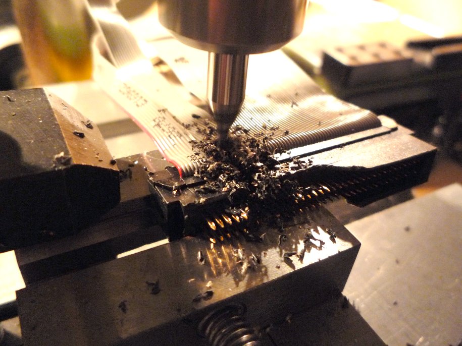 Ahh. Looks like someone lost the box with 1.27 pitch connectors ;) A wide SCSI connector helped there, so it does here: 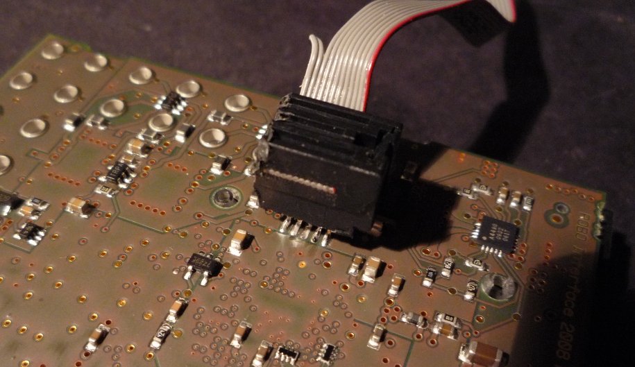
Digging deeper into this (almost) required an update of an old, well known circuit.
(Here follows a more general approach on finding the JTAG pins or pinout of foreign hardware) We will need at least:
Additionally there might be:
An ARM standardized 20pin JTAG connector looks like this (pin numbers omitted)
Although the 20pin testpoint/header pads look promising, it is not your 20pin ARM compatible JTAG port...
But wait, we still have another 2x5 pads around here.
Grab a ~47k resistor and measure pins while hardware is turned on:
Go even further, here: There are only two JTAG signals which behave like that:
To cut a long story short... 
Welcome on board...
Sample settings for J-LINK  While the flash can be accessed right away, the SDRAM of course needs some bootstrapping. SAM-BA comes with sample applet code ("board_memories.c") for a AT91SAM9260 (-EK board) with different memory. This needs to be rewritten. While the SDRAM datasheet tells us enough about the RAM itself (ROWs, COLs, TRC, TRAS, CAS-lat, ...) we still need the pins of the bus matrix (and maybe the Robo-TX standard RAM settings as well). Because you should have a working JTAG connection now, you can read out the SDRAMC from 0xFFFF EA00 - 0xFFFF EC00
and the PIOs from
0xFFFF F400 - 0xFFFF FA00
Anyway, you will need to study the AT91SAM9260 datasheet and the ARM9E-S Core(tm) TechnicalReference Manual (also available as PDF from Atmel).
Although not much nicer than before... 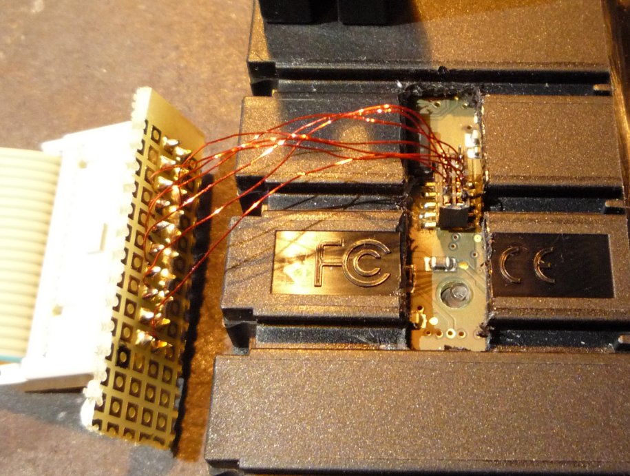
It becomes a handy HDK ;)
Customizing and compiling SAM-BA for FTs Robo-TX:If you are not familiar with ARM, toolchains, SAM-BA, etc..., here are some hints. As an exception, we are going to do this with windoze(ntm). You will need the following:
Install Sourcery G++ and test it by entering:
Install SAM-BA but do not yet start it. Depending on your budget you may use the following to hook up your Robo-TX:
If you previously attached a Lego NXT in firmware update mode, you have a little problem with the USB connection. The NXTs SAM7 comes up with exactly the same VID/PID combination. Therefore, windows does not offer you the usual "new device driver install" window but claims you attached a Lego NXT in firmware update mode:
 In this case, you need to update the driver to Atmels included "ATM6124.INF/SYS". Otherwise you will not be able to use SAM-BA via an USB connection! (Note: Keep this change of the driver in mind if you someday switch back to your Lego stuff ;-)
No matter what interface you are using:
SAM-BA asks for your connection and the attached board. Usually it fills out the right connection setting for you.
If not. Good luck debugging ;) Or even better: Use Linux! (see above for instructions on how to load the "usbserial" module).
 If all is right and windoze(ntm) is having a fine day too, you will see SAM-BA in action:
Your first SRAM readouts (9260-ek start-settings default to 0x200000): 
What you see right now, is one half of the SAM9260s internal 2x4kB SRAM (0x200000-0x201000 and 0x300000-0x301000).
Try to change the value 0x0 in 0x200020 by double clicking on it. Enter any new value and refresh the display. Easy, isn't it? Keep your mouse off the tab bar below (DataFlash, EEPROM, NandFlash, etc...). Except for SRAM, these won't work yet... Right now, you only have access to those memory areas (read the SAM9260 datasheet):
Although nothing special is working for now, you could use the two internal SRAM sections to slam in your
code. Simply use tab "SRAM", send your naked binary (un-elfed ;) type "go 0x200000" in the SAM-BA console, et voila...
Well, the weekend is already gone. Those, who are familiar with SAM-BA, can meanwhile use this to enable the Robo-TX SDRAM:
Necessary SDRAM modifications to SAM-BAs "board_memories.c."
My time is limited. More to come...
ASkr 8/2009 |