|
JTAG-Scanner
Features:
Sometimes you just need to use JTAG interfaces on foreign electronics but you have absolutely no
clue about the pinout of the connector (if any!). This is exactly what the update of UniPort (link removed) was redesigned for. A quick (and "easy" (no, not really =)) pin and port pattern generator.
Each of the (max 8) modules has 6 probing pins available.
After reducing the "premium edition" (48 fully synchronous pins on one board; multiple voltage support;
analog switches for different pull levels; RS485, RS232, I2C, SPI and parallel interface, and, and, and...)
to a more comfortable "mini-deluxe version", a modularized concept was favored.
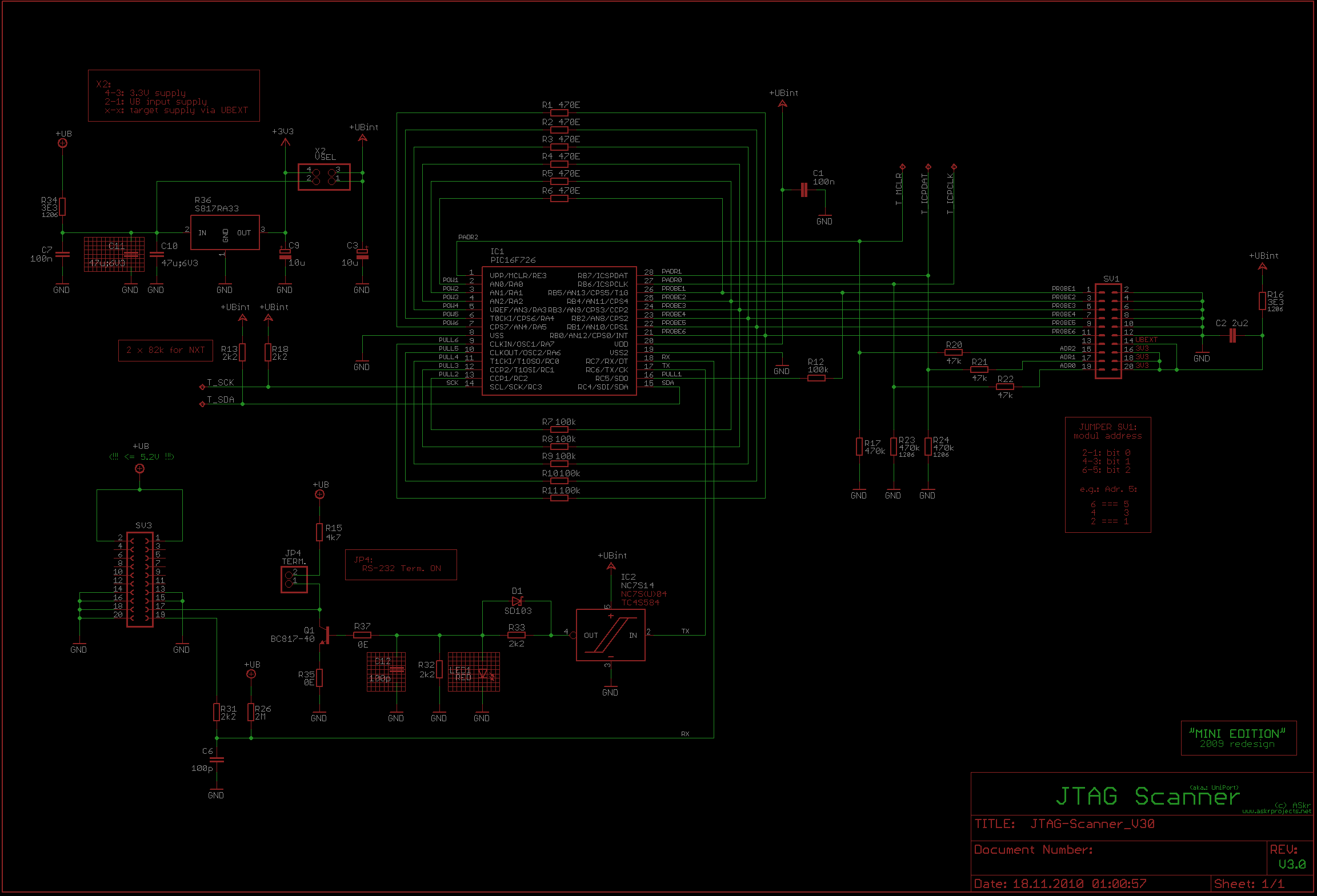
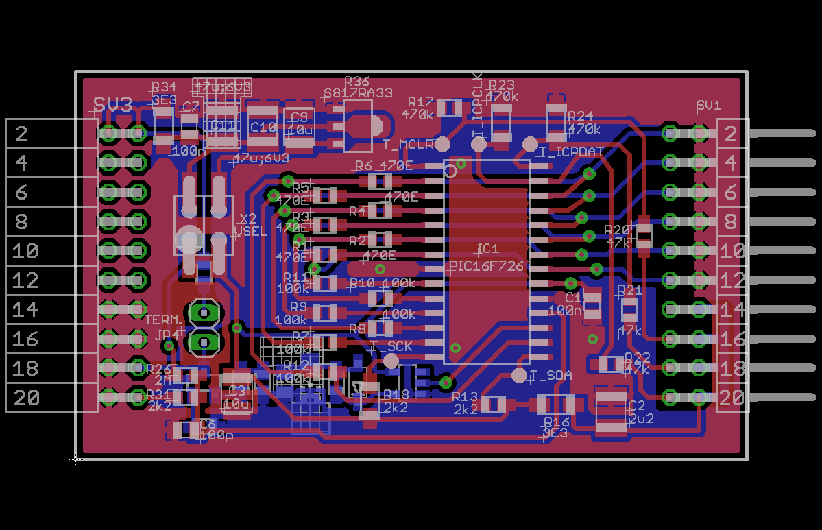
Hardware
But there were some really good reasons to do so ;-) to be continued...
Circuit Descriptionto be uploaded...
FirmwareOnly the protocol, so far:
JTAG-SCANNER PROTOCOL
=====================
  ASkr 08/2009
  ASkr 11/2010


  Minimal and confusing description of the JTAG-Scanner's protocol.


  CHANGES:
    11/2010
      - ASM firmware completely rewritten in C (Sourceboost)
      - replaced set of A/D auto trigger commands by ECMD (enhanced command, not yet implemented)
      - removed sync bits from ANSW
      - changed some other, even more confusing stuff
      - ...


PHYSICAL LAYER
--------------

   - serial interface, async, TX+RX, 8N1, baud rate 19200 bits/s (*1*)
   - host TX routed to all modules' RX line
   - module TX is open collector type to host RX


   (*1*)
   With a 16MHz oscillator, the 16F726 can not (reliably) handle any faster baud rate.
   57k6 bits/s result in 58 k8bits/s. Together with a typical FTDI, running on its internal
   RC oscillator, this may exceed the limit...


PROTOCOL
--------

   H - host, main comm interface
   M - module, on bus


     H>M
   +-----+-------+ ( -------+-- -- -+-------+ )
   | CMD | DATA0 | (  DATA1 |  ...  | DATAn | )
   +-----+-------+ ( -------+- -- --+-------+ )
     M>H (ANSWERS)
   #-------#-- -- -#-------#
   | ANSW0 |  ...  | ANSWn |
   #-------#- -- --#-------#


   COMMAND BYTE (CMD)
   +---+---+---+---+---+---+---+---+
   | 1 | A | A | A | C | C | C | C |
   +---+---+---+---+---+---+---+---+
    MSB                         LSB

      AAA  -> module address (0b000-0b111)
      CCCC -> command        (0b0000-0b1111)

   DATA BYTE (DATAn)
   +---+---+---+---+---+---+---+---+
   | 0 | S | 6 | 5 | 4 | 3 | 2 | 1 |
   +---+---+---+---+---+---+---+---+
    MSB                         LSB

      S    -> sync modifier; If set, all modules perform their action only after SYNC_PPP was received
              was received
      6    -> PULL/POW/PROBE 6
      5    -> PULL/POW/PROBE 5
     ...
      1    -> PULL/POW/PROBE 1


   ANSWER BYTE (ANSW0), GET_XXX
   #---#---#---#---#---#---#---#---#
   | 0 | 0 | 6 | 5 | 4 | 3 | 2 | 1 | probe 1..6
   #---#---#---#---#---#---#---#---#
    MSB                         LSB

      6    -> PULL/POW/PROBE_ANALOG 6
      5    -> PULL/POW/PROBE_ANALOG 5
     ...
      1    -> PULL/POW/PROBE_ANALOG 1


   ANSWER BYTE (ANSW0), READ_PROBE_DIG
   #---#---#---#---#---#---#---#---#
   | 0 | A | 6 | 5 | 4 | 3 | 2 | 1 | probe 1..6
   #---#---#---#---#---#---#---#---#
    MSB                         LSB

      A    -> analog channels involved; at least one channel is in analog mode (will report "0")
      6    -> PROBE 6
      5    -> PROBE 5
     ...
      1    -> PROBE 1


   ANSWER BYTES (ANSW0..5), READ_PROBE_ANA
   #---#---#---#---#---#---#---#---#
   |1b7|1b6|1b5|1b4|1b3|1b2|1b1|1b0| probe 1
   #---#---#---#---#---#---#---#---#
   |2b7|2b6|2b5|2b4|2b3|2b2|2b1|2b0| probe 2
   #---#---#---#---#---#---#---#---#
   ...
   #---#---#---#---#---#---#---#---#
   |6b7|6b6|6b5|6b4|6b3|6b2|6b1|6b0| probe 6
   #---#---#---#---#---#---#---#---#
    MSB                         LSB

      xby  -> 8 bit A/D values; probe x, bit y


COMMANDS
--------

     (An) -> module initiates an answer of <n> bytes, after command was sent
     (S)  -> adapted to synchronisation

         CODE | COMMAND          | DATA | DESCRIPTION
        ------+------------------+------+--------------------------------------------------------------
     (S) 0000 | SET_PULL_ACTIVE  |  1+  | activates pull-up/down resistors (0 = OFF, 1 = ON)
     (S) 0001 | SET_PULL         |  1+  | set pull direction (0 = DOWN, 1 = UP)
     (S) 0010 | SET_POW_ACTIVE   |  1+  | activates outputs (0 = OFF, 1 = ON)
     (S) 0011 | SET_POW          |  1+  | set output logic level (0 = LOW, 1 = HIGH)
         0100 | SET_PROBE_ANALOG | 1(+) | set probe channels to analog (0 = DIGITAL, 1 = ANALOG)
         0101 | SYNC_PPP         |  0   | TO ALL MODULES: execute last SET_xxx command NOW
         0110 | SYNC_PROBE       |  0   | TO ALL MODULES: execute probe measurement; analog + digital
    (A1) 0111 | GET_PULL_ACTIVE  |  0   | read state of pull-up/down resistors
    (A1) 1000 | GET_PULL         |  0   | read logic of pull-up/down resistors
    (A1) 1001 | GET_POW_ACTIVE   |  0   | read state of outputs
    (A1) 1010 | GET_POW          |  0   | read logic of outputs
    (A1) 1011 | GET_PROBE_ANALOG |  0   | read state of probe channels (state! Not their values!)
 (S)(A1) 1100 | READ_PROBE_DIG   |  0   | read logic of probe channels (digital)
 (S)(A6) 1101 | READ_PROBE_ANA   |  0   | read value of probe channels (analog)
    (Ax) 1110 | ECMD             |  n   | enhanced command follows
         1111 | RESET            |  0   | reset module; all pins float

    "1+" means: If no other command was sent in the meantime, it is still valid. Any incoming
    data byte will be interpreted as an argument to that command. These data bytes must not have
    their SYNC bit set!

    If the SYNC bit is set (DATA BYTE, b6) during a SET_XXX command, the module does not
    immediately change the outputs. The command gets executed only after a SYNC_PPP was
    received. Note: If a new SET_ (S) command is sent before SYNC_PPP, it will overwrite the
    last command.

    A SYNC_PROBE command, which does not need any address specifier, will make all modules
    read their logic probe pin state at once (digital and analog probes). The stored values can
    later be read out via READ_PROBE_DIG or READ_PROBE_ANA. Notice that the _analog_ values are not
    really measured synchronously (multiplexed A/D converter).
    If configured as digital inputs, all probe pins are samplesd at the same time.

    If a second command, with SYNC bit set, is sent, the module replaces the last stored command
    with new value received.

    ...


EXAMPLE SEQUENCES
-----------------

    a) Set outputs on module 0 to 101010 and outputs on module 3 to 010101.
       Use SYNC command to make all outputs change at the same time.
         +---+---+---+---+---+---+---+---+
         | 1 | 0 | 0 | 0 | 0 | 0 | 1 | 1 |      CMD to module 0
         +---+---+---+---+---+---+---+---+
             +---+---+---+---+---+---+---+---+
             | 0 | 1 | 1 | 0 | 1 | 0 | 1 | 0 |  SET_POW, module 0, 0b101010
             +---+---+---+---+---+---+---+---+
         +---+---+---+---+---+---+---+---+
         | 1 | 0 | 1 | 1 | 0 | 0 | 1 | 1 |      CMD to module 3
         +---+---+---+---+---+---+---+---+
             +---+---+---+---+---+---+---+---+
             | 0 | 1 | 0 | 1 | 0 | 1 | 0 | 1 |    SET_POW, module 3, 0b010101
             +---+---+---+---+---+---+---+---+
         +---+---+---+---+---+---+---+---+
         | 1 | X | X | X | 0 | 1 | 0 | 1 |      SYNC_PPP -> previous (S) commands are executed at once
         +---+---+---+---+---+---+---+---+                  X -> don't care

    b) Toggle some outputs on module 6; not synced
         +---+---+---+---+---+---+---+---+
         | 1 | 1 | 1 | 0 | 0 | 0 | 1 | 1 |      CMD to module 6
         +---+---+---+---+---+---+---+---+
             +---+---+---+---+---+---+---+---+
             | 0 | 0 | 1 | 1 | 1 | 0 | 0 | 0 |  SET_POW
             +---+---+---+---+---+---+---+---+
         +---+---+---+---+---+---+---+---+
         | 1 | 1 | 1 | 0 | 0 | 0 | 1 | 1 |      CMD to module 6
         +---+---+---+---+---+---+---+---+
             +---+---+---+---+---+---+---+---+
             | 0 | 0 | 0 | 0 | 0 | 1 | 1 | 1 |  SET_POW
             +---+---+---+---+---+---+---+---+
             ...

    c) Change logic state on module 0, probe 1. Read back synced probe pins from module 1 and 2.
       SYNC_PROBE commands all modules to sample their probes. The results can later be fetched
       via READ_PROBE_DIG/ANA
         +---+---+---+---+---+---+---+---+
         | 1 | 0 | 0 | 0 | 0 | 0 | 1 | 1 |      CMD to module 0 (SET_POW, an (S) command)
         +---+---+---+---+---+---+---+---+
             +---+---+---+---+---+---+---+---+
             | 0 | 0 | 0 | 0 | 0 | 0 | 0 | 1 |  SET_POW, module 0, probe 1 high
             +---+---+---+---+---+---+---+---+
         +---+---+---+---+---+---+---+---+
         | 1 | X | X | X | 0 | 1 | 1 | 0 |      SYNC_PROBE, all modules ----------------------+
         +---+---+---+---+---+---+---+---+                                                    |
         +---+---+---+---+---+---+---+---+                                                    |
         | 1 | 0 | 0 | 0 | 0 | 0 | 1 | 1 |      CMD to module 0 (SET_POW, an (R) command)     |
         +---+---+---+---+---+---+---+---+                                                    |
             +---+---+---+---+---+---+---+---+                                                |
             | 0 | 0 | 0 | 0 | 0 | 0 | 0 | 0 |  SET_POW, module 0, probe 1 low                |
             +---+---+---+---+---+---+---+---+                                                |
         +---+---+---+---+---+---+---+---+                                                    |
         | 1 | 0 | 0 | 1 | 1 | 1 | 0 | 0 |      CMD to module 1 (READ_PROBE_DIG) +------------+
         +---+---+---+---+---+---+---+---+                                                    |
             #---#---#---#---#---#---#---#---#                                                |
             | 1 | 1 | 1 | 0 | 1 | 0 | 1 | 0 |  ANSW from module 1 ---------------------------+
             #---#---#---#---#---#---#---#---#                                                |
         +---+---+---+---+---+---+---+---+                                                    |
         | 1 | 0 | 1 | 0 | 1 | 1 | 0 | 0 |      CMD to module 2 (READ_PROBE_DIG) +------------+
         +---+---+---+---+---+---+---+---+                                                    |
             #---#---#---#---#---#---#---#---#                                                |
             | 1 | 1 | 0 | 1 | 0 | 1 | 0 | 1 |  ANSW from module 2 ---------------------------+
             #---#---#---#---#---#---#---#---#
to be continued...
Softwareto be uploaded...
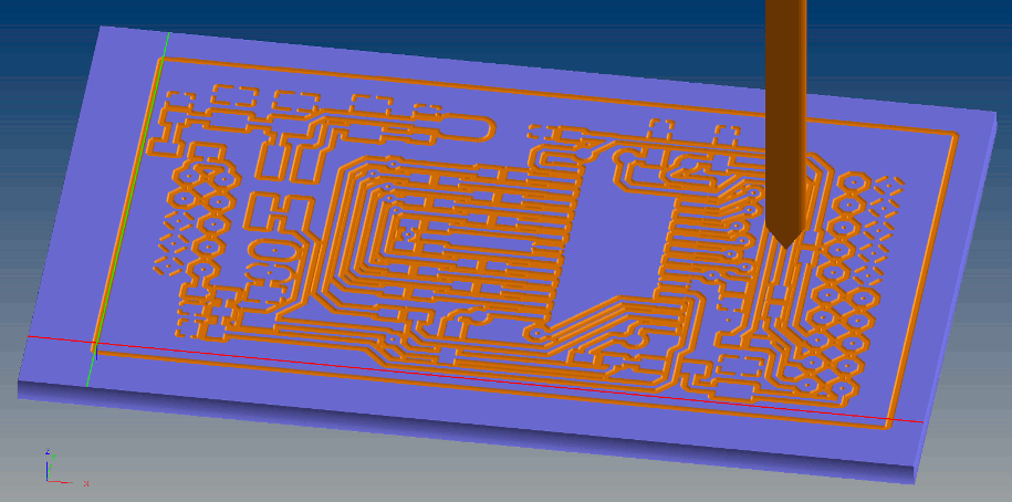
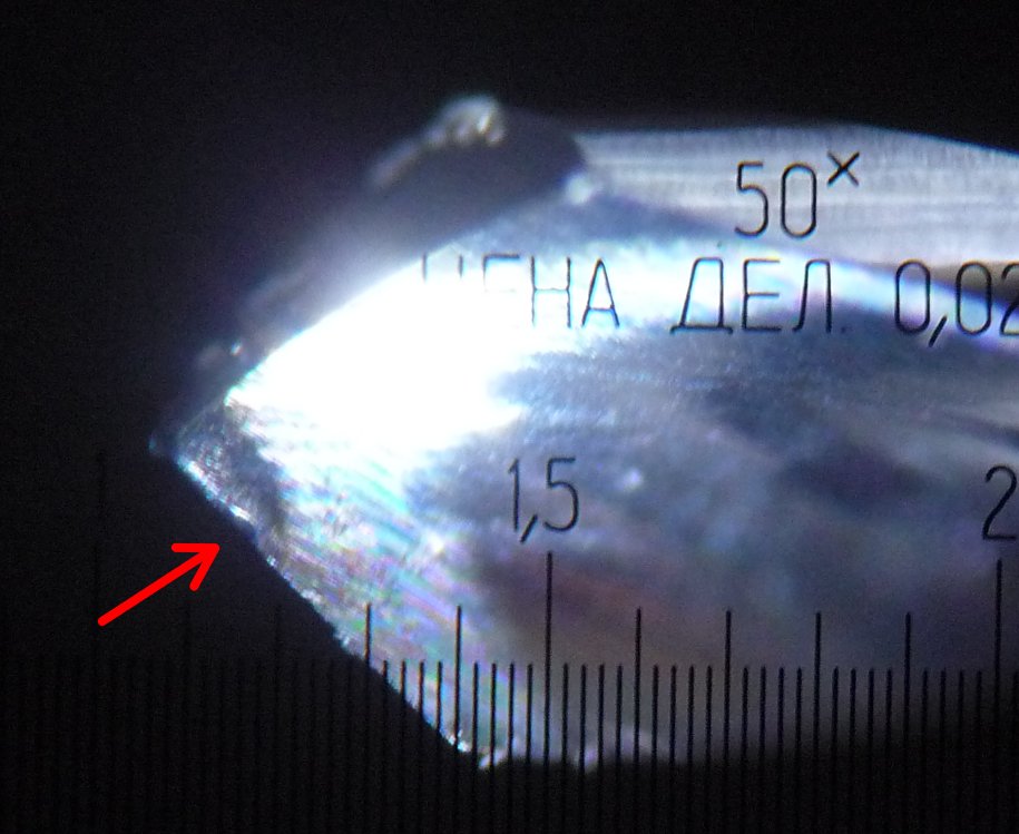
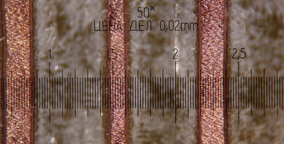
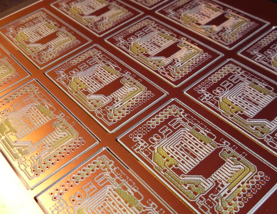
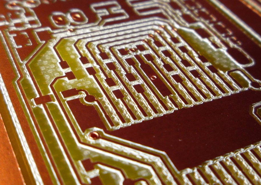
Useless Pics
Download
JTAG-Scanner V3.0:
DOWNLOAD: JTAGScanner_hard_V30.zip HW; V3.0 |