MetalEars - Headphone amplifier #19, with the right punch for down tuned, brutal and distorted guitars.
As a musician and engineer, I am not afraid of tone controls.
If you are, this is probably not the right place for you...
(Though MetalEars still is an excellent amplifier with all that tone-stuff removed...)
Input and Filter Stage
MetalEars schematic, 1/2
MetalEarsPA-XFEED, 2/2
The input connection, usually your CD, DAT, DVD or whatever-player, first hits C5 for
DC-decoupling, with a -3dB corner frequency of ~1.5Hz (C5, R4+R7).
Additionally, R4 and C7 form a simple low-pass filter with a corner frequency of ~48kHz.
As an alternative, R7 can be replaced by a potentiometer (47k) for an input balance
control and gain adjustment.
Notice the alternative component values for a lower input impedance.
IC2, the first OPA134, only acts as an
impedance converter, which is required for the next stage.
Filter Stage (low section)
Some headphones, especially the "good ones", sound too bright for distorted guitars.
If you want a treble/presence sink added to the circuit, fit R3L/R, R1, C1 and R2L/R.
If you don't need this feature, leave all these components out and short IC2-6 with IC1-3.
For the upcoming discussion about the bass-boost functionality, we simply assume that the
upper part of the connection IC2-IC3 is not present or the potentiometer R3L is turned
towards IC2.
In the image on the right, Za and Zb represent the potentiometer with its middle tap
shorted to ground via an impedance. Even without calculating the circuit, it is obvious
that the output follows the input if the following conditions are met:
- Z is not present or Z -> ∞
- the potentiometer is turned all way left (Za = 0)
In all other cases, the output voltage can be calculated by:
With the potentiometer turned to the left (Za = 0):
And to the right (Zb = 0):
Well, this looks familiar. Even with the presence of Za, we now have a standard
non-inverting topology. By turning the potentiometer from the left to the right,
the amplification V can be varied from V=1 to V=1+Zg/Z.
If we replace Zg by a resistor Rg and Z by an inductor
the transfer function ua/ue (with Zb = 0) becomes
which represents nothing else but a first-order low-pass filter:
normalized transfer function, Rg = L = 1
Adding the potentiometer value(s) as a parameter to the complete formula,
with Rg = L = 1, Ra = n*Rp, Rb = (1-n)*Rp, Rp = 1
With an additional resistor in series with the inductor, to limit the gain
and assuming that Rg = 10 * R (rest like above)
By changing the values for the inductor (L'=L, L'=L/5 and L'=L/20), the
corner frequency can be varied:
With a little more clever settings for Rg and Zp, the potentiometer value, we
get a more "exponential feeling". Turning the knob towards zero (left), results
in a finer adjustment.
A good starting point for doing so is to consider the gain with the potentiometer
set to the middle:
With Zp = 3*Zg, the results are looking promising (and sound right while
turning the baaad knob):
Now, the optimal corner frequency range (+3dB gain point) for the baaad bass boost
knob, highly depending on the attached headphones, is somewhere between ~100Hz and
400Hz (2kHz while adjusting, see below).
The most common setup procedure is to start with the highest frequency available, so
you clearly can hear where the mids stop while turning the knob counterclockwise.
At least, I prefer this method. The upper +3dB point is intentionally set to
an outrageous frequency of ~2kHz.
For a gain of ~20dB (Rg/R = 10), Rg set to 3k3 and a corner frequency of 100Hz,
would require a giant inductor of ~5H:
Wow ;) And even for 2kHz, an inductance of ~260mH would be required.
Obviously, there's no (practical) way of building such an inductor, but fortunately
one can build an active circuit that simulates an inductor.
a negative impedance converter (NIC)...
|
... and a real gyrator
|
While a NIC creates a negative impedance, a gyrator, built of two NICs, can transform
an impedance to its inverse. Placing a capacitor in there transforms it into an inductor:
With only a few uFs, quite large impedances can be built.
Unfortunately, the only way of changing the value of the inductor is to change
multiple Rs altogether.
Additionally, two more opamps would be required.
As an alternative, not-that-perfect-circuits can do the same with a single amp.
With a clever value selection all parasitic residuals can be neglected:
gyrator, type I
|
gyrator, type II
|
TYPE II:
The result is an inductor with a resistor of value R = Z1+Z2 in series with it.
The ratio of the inductance and resistance is not that brilliant...
TYPE I:
Which results in the equivalent circuit:
The resistance in parallel to the inductor requires special attention. If it becomes
too low, the filter stage will amplify the mids and highs too.
You can actually see (or hear) this happen if you stick to the 82n/100k combination.
max values; 82n/100k; potentiometer set to left, mid and right
With the alternative values applied (15n/1M):
max values; 15n/1M; potentiometer set to left, mid and right
...
Filter Stage (high section)
This is not a serious (HiFi) tone control. Its for musicians and those that would like
to damp the higher frequency components.
After all that LaTeX typesetting for the bass-boost section, I am going to skip these
for the treble/presence cut circuit.
Basically, it operates exactly like above with the exception that it will only sink, not boost.
For real-world measurements, scroll down...
Although this part of the circuit can be left out, it might help limit the intense, bright sound
some headphones produce. If you decide to left it out, replace potentiometer R3 with a wire.
max values; potentiometer set to left, mid and right
...
Amplifier
Although almost every amplifier can be attached to the filter
stage, assuming an adequate gain (0..20dB, depending on the input signal of the
signal source and the ratio of the "bass boost"), I wanted something new.
I never designed a headphone amplifier with nothing else but some opamps
in the last stage. I usually prefer transistors ;)
Well, on to something "new".
A single, standard amp does not provide enough power for low impedance cans (*1*).
But from all I learned during the last 18 designs, the only way of supporting all
headphones (in terms of output level, distortion, 82 other parameters and - well, "sound")
is to reduce the amplifiers output impedance (far) below 10 Ohms.
A common practice for obtaining more output is to put multiple amplifier stages in parallel,
each stage decoupled with a (lower) 2-digit resistance.
Usually, one uses the standard impedance converter (aka.: unity gain buffer/follower) topology (V=1; see left image).
The standard topology.
Multiple, decoupled impedance converters.
|
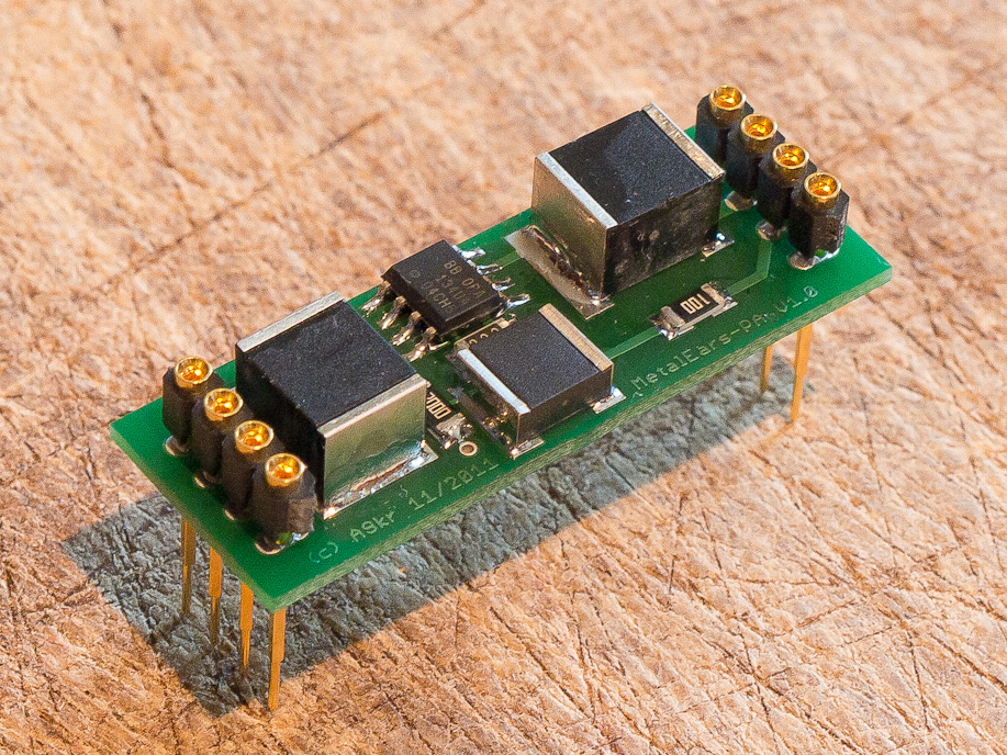
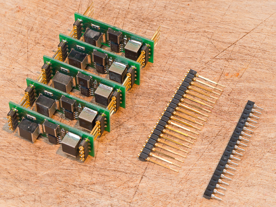
The test object.
Decoupled non-inverting stages.
|
A true no-brainer. No additional components, simple to build, no additional noise
components... Almost perfect!
"Almost?"
- gain is 1 (0dB); we need more; additional stage required
- no bandwidth limit; opamps working at full speed
- (There's a lot more, but all of this would apply to any other topology too...)
A gain of 0dB is not enough, so what about combining amplifiers with a non-inverting topology,
as shown in the image on the upper right?
Well, noise and distortions would rise, but how much?
And no matter if we choose the left or the right design, which opamp is the best one?
Which one can drive the lowest impedances and offers the lowest distortion?
Let's find out...
...
===
(*1*) Note to brain: Insert impedance measurements here...
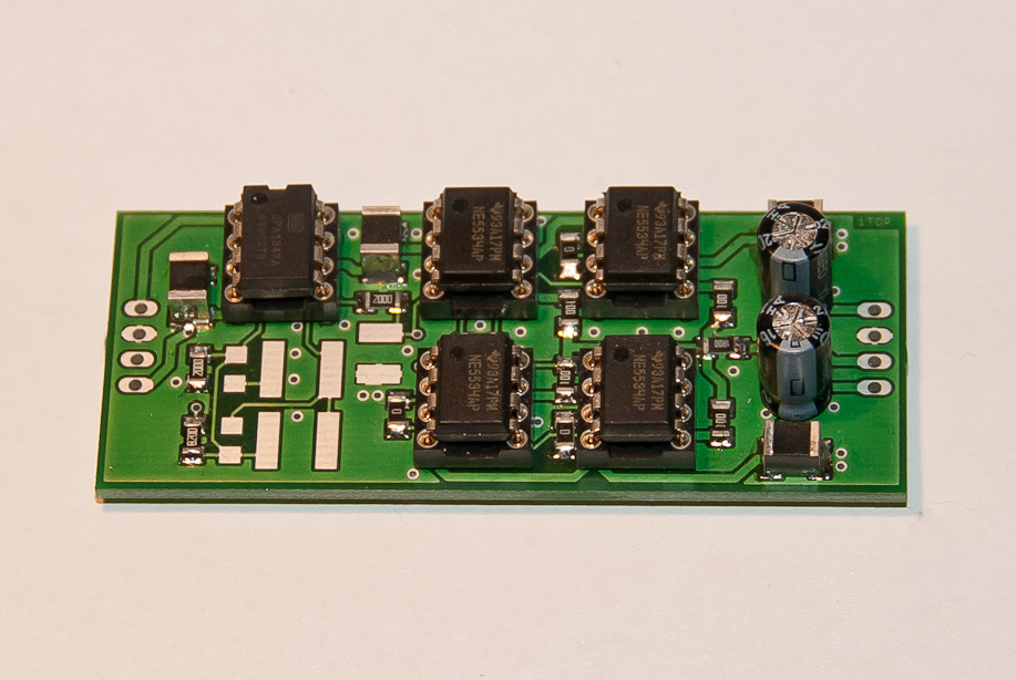
OpAmp Tests
test circuit #1; 2 amplifiers in parallel
(PS bypassing/decoupling Cs not shown)
We'll start off with a standard non-inverting design.
The opamp test circuit above offers two gain settings:
- 0dB if the switch is closed (Rload ~ 35E)
- 24dB as shown above (Rload ~ 55E)
Notice that the input potentiometer (10k) was set to "maximum level" for the impedance converter
and 1/16 of its value for the 24dB circuit, an additional handicap for the latter circuit
(except CMRR).
For all measurements:
- average of 2x2 opamp circuits
- 0dBrms output level
- THD vs. amplitude at 1kHz
- IMD vs. amplitude at 60/7000Hz, 4:1 (SMPTE)
- label "IMPCONV": impedance converter circuit
- label "GAIN=0dB": 24dB circuit
- Rload as above
All measurements were done with:
test setup #1
The setup was available, so I additionally hooked up opamps like the TL071, LT1007 or
LF351 and others, just to see how they perform under load (probably only a few would consider using one of these for
a "power" amplifier ;-)
IN NO PARTICULAR ORDER
(and not commented, 1/2012):
TS912
THD, imp.conv.
|
THD, 24dB

|
IMD, imp.conv.
|
IMD, 24dB
|
TL071
THD, imp.conv.
|
THD, 24dB

|
IMD, imp.conv.
|
IMD, 24dB
|
PC4570
THD, imp.conv.
|
THD, 24dB
|
IMD, imp.conv.
|
IMD, 24dB

|
OPA627
THD, imp.conv.
|
THD, 24dB
|
IMD, imp.conv.
|
IMD, 24dB
|
OPA37
THD, imp.conv.
|
THD, 24dB

|
IMD, imp.conv.
|
IMD, 24dB

|
OPA134
THD, imp.conv.
|
THD, 24dB
|
IMD, imp.conv.
|
IMD, 24dB

|
NJM4580
THD, imp.conv.
|
THD, 24dB
|
IMD, imp.conv.
|
IMD, 24dB

|
NJM4560
THD, imp.conv.
|
THD, 24dB
|
IMD, imp.conv.

|
IMD, 24dB
|
NJM2068
THD, imp.conv.
|
THD, 24dB
|
IMD, imp.conv.
|
IMD, 24dB
|
NE4558
THD, imp.conv.
|
THD, 24dB
|
IMD, imp.conv.
|
IMD, 24dB
|
NE5534
THD, imp.conv.
|
THD, 24dB
|
IMD, imp.conv.
|
IMD, 24dB
|
LT1007
THD, imp.conv.
|
THD, 24dB

|
IMD, imp.conv.
|
IMD, 24dB

|
LM301
THD, imp.conv.
|
THD, 24dB
|
IMD, imp.conv.
|
IMD, 24dB
|
LF351
THD, imp.conv.
|
THD, 24dB
|
IMD, imp.conv.

|
IMD, 24dB
|
AD797
Well, there's something wrong here ;)
THD, imp.conv.
|
THD, 24dB
|
IMD, imp.conv.
|
IMD, 24dB
|
LM4562
THD, imp.conv.
|
THD, 24dB
|
IMD, imp.conv.
|
IMD, 24dB
|
The final amplifier: XFEED-PA
All the insights derived from the previously measured data resulted in a brilliant
power amplifier section with really excellent benchmarking data.
All measurements were done in the really not clean lab-environment (spikes at 50Hz, 300Hz-1k, etc...).
If necessary, "extra stability components" (e.g. compensation capacitors, etc...) were added.
MetalEarsPA-XFEED schematic...
|
...and layout
|
THD vs AMP, 1kHz, 25 Ohms load
|
IMD vs AMP (SMPTE), 1kHz, 25 Ohms load
|
THD, 1k, 0dBV, 25 Ohms load
<0.0003%
|
THD, 60Hz, 0dBV, 25 Ohms load
<0.0015%
|
THD, 6k, 0dBV, 25 Ohms load
<0.0006%
|
THD, 9k, 0dBV, 25 Ohms load
<0.0007%
|
IMD (SMPTE), 0dBV, 25 Ohms load
|
IMD (SMPTE), zoom 6..8k, 0dBV, 25 Ohms load
|
magnitude, ~0dBV, 25 Ohms load
0.1dB, 20Hz..30kHz
|
phase, ~0dBV, 25 Ohms load
5°, 20kHz
|
(((Insert stability stuff, right here...)))
Even with an outrageously large capacitive load of 100nF at the output,
everything remains stable.
load test; Rl=25E; Cl=0
f=33.33kHz; gain=3.3; rise time 10ns
Ub = +-8.6V (NiMH)
|
cap load test; Rl=25E; >>Cl=100nF(!)<<
f=33.33kHz; gain=3.3; rise time 10ns
Ub = +-8.6V (NiMH)
Disappears below 580mVrms
|
...
Other
to be uploaded...
|