PRE
PRE V1.1 schematic...
|
...and layout

|
The incoming signal from the electret microphone
first hits C4, which removes RF components. R1, R2 and C1 form a filtered power supply path for
the mic.
Almost any electret mic capsule, with a diameter ~10mm, can be used. For some rare
(usually the good and pricey ones) types, it might be necessary to decrease R1 and R2 until
the static DC voltage at X2-1 matches to the microphone specs (typically >=1.5).
Because we'll only use a single voltage supply (a standard 9V battery is all we need) the signal
needs to be shifted to half the operating voltage before it is amplified:
While C2 removes the DC component of the signal (the power supply of the microphone), R3 and R4
pull the signal right to the middle (~4.5V).
Additionally, these three components form a low pass filter with a corner frequency of ~310Hz.
The LT1007, including R5, R6, C5 and C6
("DC free", non-inverting amplifier) boosts the signal by ~40dB (V=~100), adds a second low pass
(R6, C6) and a high pass filter (R5, C5).
The result at pin 6 of the operational amplifier is a 100 times boosted signal including
a 4.5V offset. The latter is removed ("blocked") by C3.
Note the component value changes in the schematic if you only want to build the single PRE version.
In this case, also skip the external potentiometer!
An external, completely DC-free, potentiometer (10k, log) connects PRE and POST.
===
ADDITIONAL NOTES:
You might wonder about the "THIN FILM" attributes of R3, R4 and R6, but they really will
improve the signal to noise ratio
of the circuit.
Standard chip resistors usually are fabricated in a thick-film process, which will add
significantly (10 up to 100 times) more noise. If you build the circuit with through
hole components, simply use 1% metal film resistors.
All other components noise contribution, except for the microphone itself, can be neglected:
noise contribution of:
R3/R4 (red), R6 (cyan)
microphone, 2k (purple)
While reducing the resistor values for R3 and R4 (or R6) would improve the noise figure of the circuit,
higher impedance microphones will not benefit from this:
- the noise of the microphone is much higher
- the signal will get damped by the low input impedance of R3/R4
If you decide to decrease R3/R4, also change C2 accordingly (C2 = 1 / ( 2*pi * R3/2 * 310 Hz ).
If you manage to find an >2u2, 0805, X7R capacitor, you can do the same with R5, R6 and C6:
- maintain the ratio of R5/R6
- maintain an inverse ratio of R6-C6 (if you half R6, double C6)
- beware of the limited output power capability of the LT1007
POST
POST V1.1 schematic...
|
...and layout
|
There is not much to say about this driver stage...
Two parallelized halfs of a NJM4556,
a dual, high output power OP, will directly drive any headphone type.
Gain is set to ~20dB (V=10), resulting in a grand total of ~60dB (V=1000, including PRE).
If that's not enough, decrease R5/R8 down to 1k for a total gain of ~66dB (V=2000).
Including the filters of the POST stage, we now have a nice, human voice matched
frequency response:
overall frequency response
blue: in (-60dB)
|
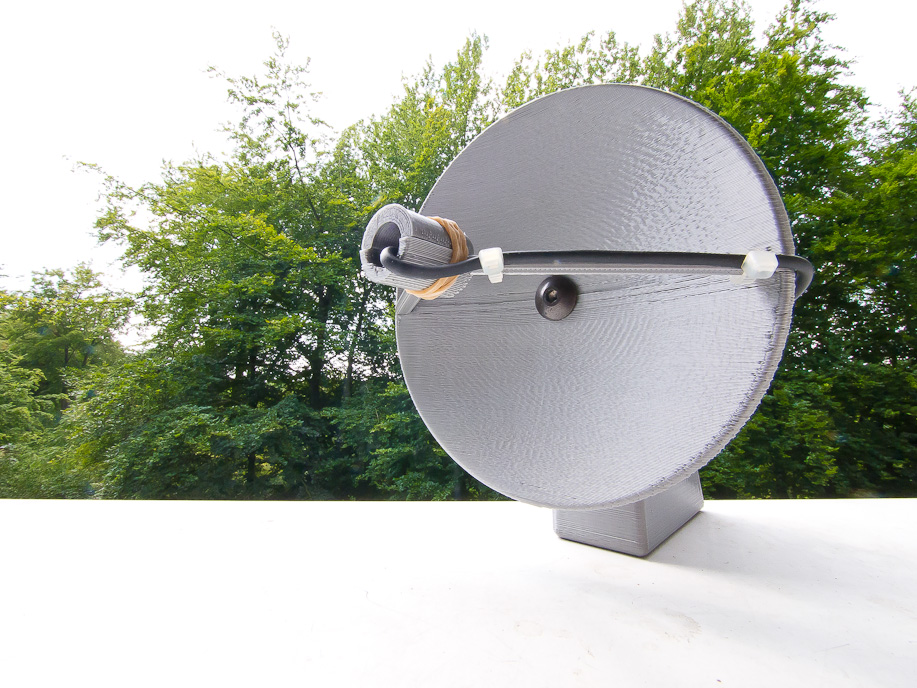
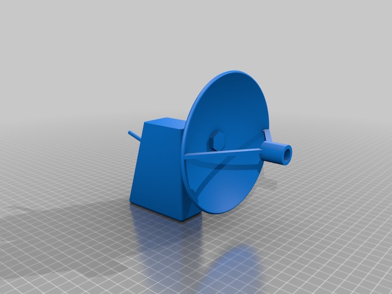
Mechanic
The mechanic consists of five, printable parts:
ParaMike overview
|
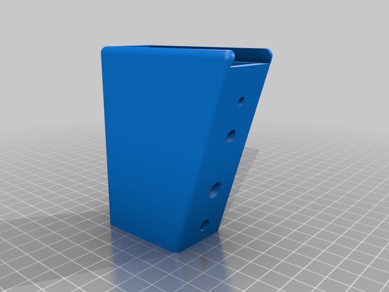
handle
|
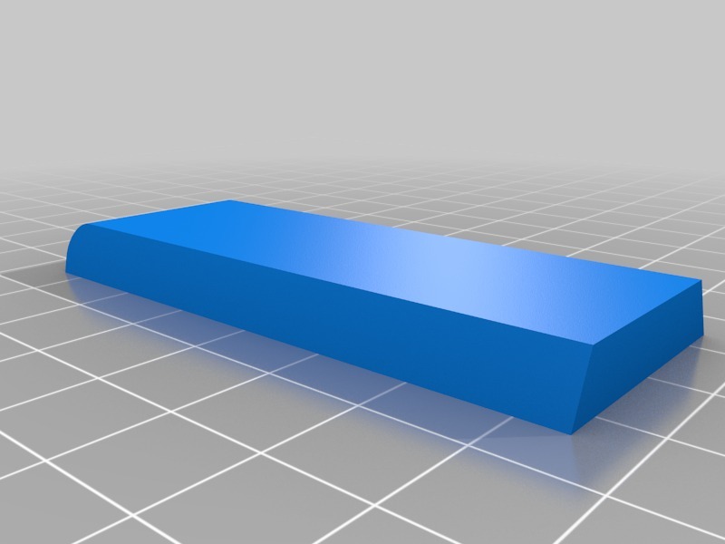
cap (battery compartment)
|
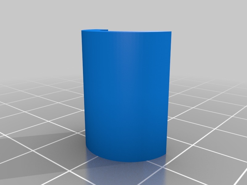
mic. fixture
|
mirror bottom
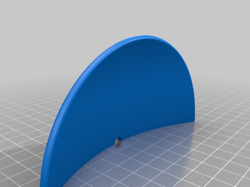
|
mirror top
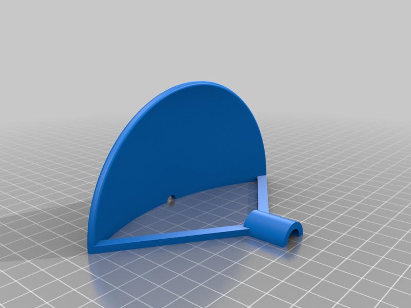
|
Unscaled and as presented here, the parabolic mirror diameter measures to 125mm, a quite
ridiculous small value.
Good news:
You can scale it to whatever diameter you like. Only the size of your printer limits you.
Note: Handle and cap should not be scaled, only the mirror.
Firstly, print all parts.
Glue both parts of the mirror together.
The mirror has a 6mm hole to mount the handle. Put a screw (or a thread) through both
and fix it with three 6mm nuts. Two of them go between mirror and handle, the last one to the back of the handle.
If you enlarged the mirror, the diameter of the hole in the mirror increased too.
If the hole got too large, use two washers.
Two options for the microphone:
You can either solder a one-pole, shielded cable to it and put the PRE electronic in the handle or
you can solder the microphone to the PRE PCB and mount it altogether (the latter requres a two-pole,
shielded cable).
No matter which option you choose, wrap a bit (or more if you enlarged the diameter of the
mirror) of cotton around the microphone. This helps damping impact sound.
Put the fastener (a half tube) over it and fix it with a rubber band, cable strap or tape.
One side of the microphone holding bars has a cable conduit (cut-out) towards the inside.
Thread the cable along this conduit, through the hole in the mirror and, last, the hole in
the handle. If you did not enlarge the mirror, the cable consuit will only take a very thin
(~1mm diameter) cable.
Build all the electronics and stick it in. Beware of short circuits and
wrap isulating tape around the PCBs.
The rear of the handle has four holes. From top to bottom:
- mirror mount
- 4mm potentiometer, 7mm mount
- toggle switch, one-pole, 5mm mount
- hole for cable with 6mm or 3.5mm jack socket
Before putting in the battery, stick some cotton into the handle.
ParaMike-Thing on Thingiverse.
|