UniTHAmp - a simple, universal "one size fits all" amplifier board.
Features:
- simple through hole (TH) desgin
- covers 99% of standard opamp configurations
- single supply
- dual supply
- non-inverting
- inverting
- differential
- input and output filter
- AC or DC operation
- boards can be directly connected in parallel or series
- ...
Beside its standard lab usage, look out for upcoming, advanced attractions using UniTHAmp:
- HeadPAmp #37; headphone amplifier design number 37; including parametric bass equ
- nMeas; a set of hard- and software for noise measurements
- ...
Hardware
V2.0 schematic...
|
...and layout
|
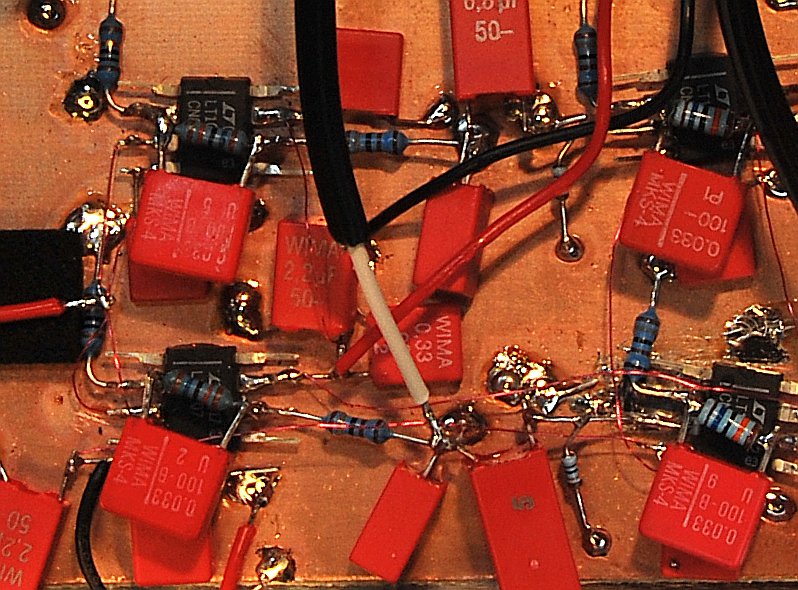
While sitting in the lab, you'll sooner or later end up wiring required tools like this:
I had a stock of ~100 universal amplifier boards, which I created about 10 years ago. Last month, the
last board successfully replaced a blown up LCD contrast regulating unit in a printer.
A replacement was badly needed...
No matter if you quickly need
- a measurement amplifier,
- opamp test or selection board,
- a headphone amplifier,
- a quick and dirty (low) current sink,
- a photodiode amplifier,
- audio distribution devices,
- or tons more of other stuff,
an UniTHAmp (almost) covers it all.
Circuit Description
|
Components
Throughout the design, all capacitors have 5mm spacing, all resistors have 7.5mm.
5mm spacing for capacitors allows usage of high(er) quality polypropylene or
polystyrene film types and 7.5mm for resistors, well - this offers much quicker bending ;)
Single or dual supply
All power supply terminals, "+UB", "-UB" and GND are available on both sides of the PCB.
For single supply operation "-UB" and GND need to be shorted. You can either connect them
right at the input pads, short C6 or scrape off the solder resist adjacent to pin 4
of the opamp.
For dual supplies, both blocking capacitors C1 and C6 should be fitted (even large
polystyrenes up to 10uF can sit there), for single supply operation only C1 is required.
Input
The negative input "IN-" is limited to a single resistor (R14). Additional capacitors
can either be cennected externally or wired back to the R1-R8 junction with R4 removed.
In this case, C4 would probably be replaced with a resistor (or short circuit) to ground.
The positive input "IN+" offers much more flexibility:
R6 can be useful as an input termination, a divider (assuming the previous stage has
a resistor connected in series to its output) or a high-impedance discharge resistor
for C2, if the board is disconnected.
For straight DC operation, only R2 and R4 are required. For AC operation, C2 acts as
a DC decoupling capacitor and R1/R8 or R7 set the DC offset.
Every good design needs an input filter. The simple R4/C4 combination takes care of that.
Feedback/Output
For standard, non-inverting configurations, only R9 and R12 (maybe R13) are required.
Notice that R12 has a GND via under it, hence R13 is not mandatory.
C5 offers band width limitation (creating an additional pole in the transfer function),
C7 is needed in single supply configurations (DC decoupling).
Instead of using the standard layout, the feedback path can also be closed via R10
(instead of R9 or in conjunction with it), which might come in handy for
heavy or capacitive loads without reducing the DC or LF precision.
In addition to all of the above, R5/C10 create a simple low pass filter, R3/C3 determine
if AC or DC output is required and last, R11 provides an output termination or C3
discharge option.
Several additional ground connections beneath the components (marked as "(X)") offer
additional ground connections (E.g. a second output filter stage by replacing R11 with
a capacitor, and, and, and...).
C8, C9
C8 and C9 are reserved for special opamps, e.g. LT1028 or LT1007, ...).
The board intentionally does not contain any offset circuitry. This needs to
be wire wrapped (*1*).
===
(*1*) In >98.2% of all cases, a wise design redundantizes all potentiometers, saving
costs and time.
Additionally, some day, some idiot will take a screwdriver and "make adjustments" (...).
|
Cascading
|
in parallel
Sometimes it is desired to have multiple boards in parallel :
- higher output power
- reducing amplifier noise
- signal distribution
- ...
UniTHAmps are stackable. Stick wires through the holes and solder them (or use plugs).
...
|
|
in series
At least for non-inverting configurations, multiple boards can directly be wired
in series. For inverting operation at least a small wire ("IN-" to "OUT" of the
previous board) is required.
...
|
Examples
to be uploaded...
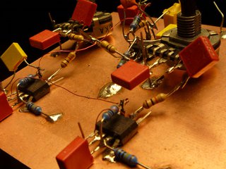
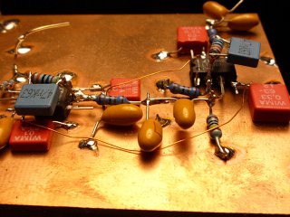
Some Useless Pics
a typical application for UniTHAmps ;)
|
3 modules in series/parallel

|
Download
UniTHAmp:
Includes:
- schematic (PDF)
- placement drawing (PDF)
- layout, Eagle (BRD)
DOWNLOAD: UniTHAmp_hard_V20.zip Hardware, V2.0
ASkr 07/2011: initial public release HW V3.0
|