RX1, The Beginning
RX1 detects the direction of one or more transmitter(s) by measuring the signal intensity at
at four different angles. Thanks to a tiny, but powerful
dsPIC,
all channels are sampled simultaneously and analyzed by a real-time
Goertzel-Algorithm.
If more than one TX1-beacon in DTMF-mode is in the reception range of the receiver,
it can only distinguish those with unique frequencies:
- 1, 5, 9, D
- 4, 8, #, A
- 7, 0, 3, B
- *, 8, 6, A
- ...
This issue got addressed with the TX1-RX2 combination (upcoming attraction).
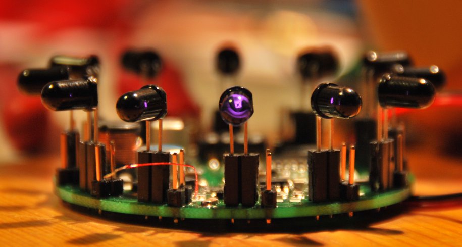
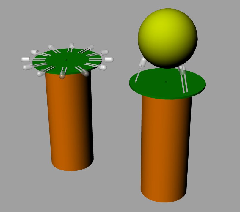
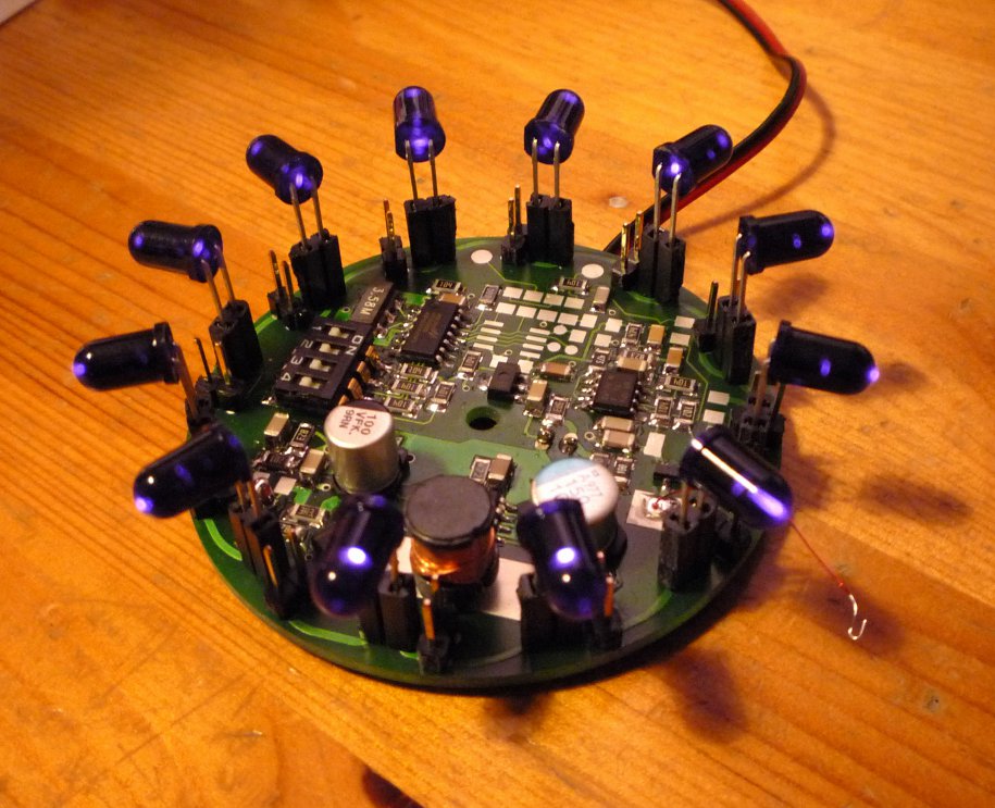
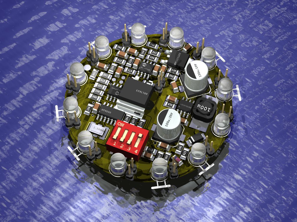
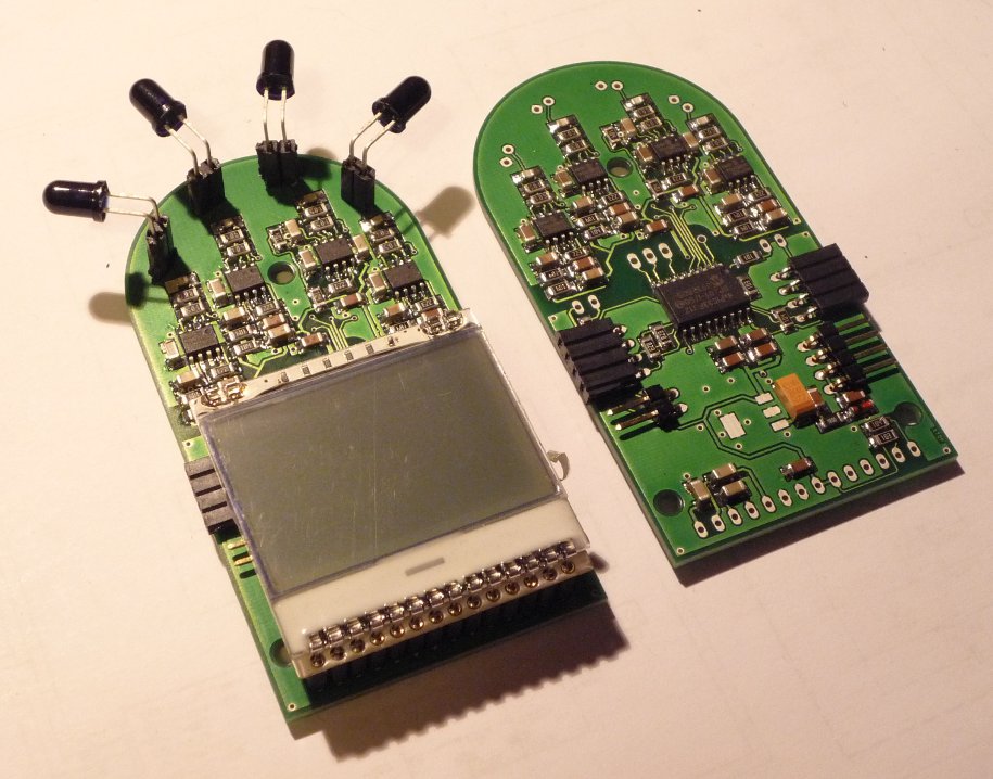
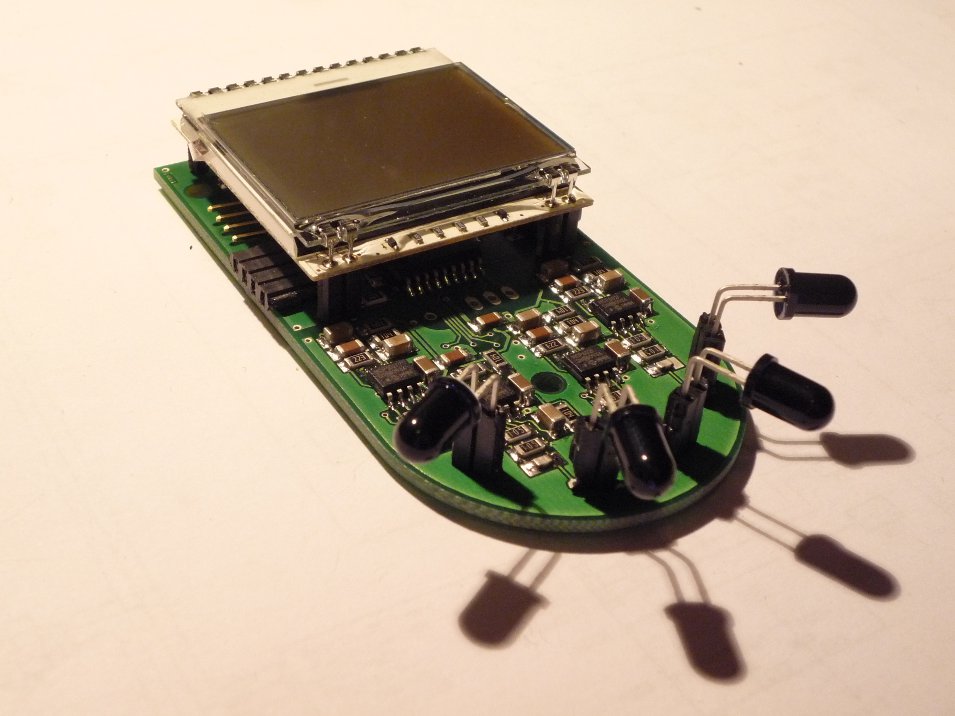
The photodiodes used (SFH203FA), have a 50% intensity angle of +-20°. Each of them is mounted with an angular offset
of 40° to the adjacent one. Theoretically, this results in a constant, summed up signal level across rotation.
In practice, it requires bending, twisting and slapping ("fiddling around with photodiode position")
the diodes until they are where they belong.
The differential signal input of two (or more) adjacent diodes is not used for position detection,
only for a quick, first "guess" across an angular span of 160°.
For operation, only one diode would be required, but four speed up things dramatically...
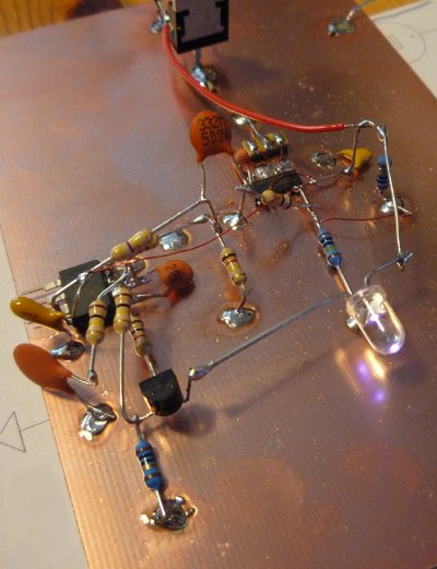
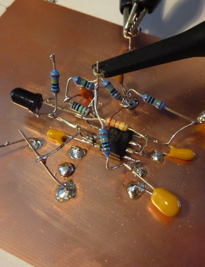
RX1 schematic...
|
... and test layout
|
The circuit consists of four equal detection circuits (CH1-4).
A standard photo detector circuit (aka "I-U converter"), formed by one half of the MCP602
(R1, D1) directly feeds the A/D input of the dsPIC.
Because only a single supply is available, R2, R5 and C4 provide an 1.65V offset for the circuit.
The output signal, including the offset, is filtered by R4 and C5 (arithmetic mean,
time constant ~10s (a little large, I agree ;-)) and fed back to the negative input of the photodiode
amplifier via the second half of the MCP.
This way, any (speak: most of the) DC offset, caused by ambient light, will be corrected to 1/2 of the supply voltage.
The dsPIC provides a serial (115k, 8N1), as well as an I2C interface. For NXT compatibility, choose
R23 and R24 to 82k. For real world I2C interfaces, reduce them to ~2k2-10k.
The processor had some spare pins left, so a
tiny LCD was added to the test layout. It has to be mounted via IC-sockets
or stuff like this.
to be continued... (11/2010)
noisy signal; 5kSps; 0.2s; float
|
clean signal; 5kSps; 0.2s; integer
|
real HW/FW sweep; 5kSps; 0.2s; 1Vpp input
|
like above, enlarged
|
like above, enlarged
|
like above, enlarged
|
The Scilab scripts, whose produced the simulations and the dsPIC captured frequency sweep,
can be downloaded here. They may provide a good start understanding (and fiddling around with)
the Goertzel algorithm.
Firmware RX1
DTMF mode display
|
sweep display
|
5 bytes left; mission accomplished ;-)
|
Number of Goertzel steps (samples) and effects.
Download this Scilab script here,
or use SiSeLi ;-)
Notice that the output values are NOT NORMALIZED (divided by the number of samples)!
Use the source ;-)
to be documented... (11/2010)
incredible, that's from 2010? (5/2012 ;-)
Commands
    HOTKEYS (UART, 115200,8N1 or I2C):
    =================================

     ESC  stop (after current operation)

      d   DTMF mode, all channels (4), all frequencies (8)
      D   DTMF mode, single shot
      s   sweep mode
      S   sweep mode, single shot

      a   sweep output for all channels (only serial)
      0   sweep output for one channel only

      c   sweep channel selection (one channel); requires IDLE_STATE; followed by:
        1    select channel 1
        2    select channel 2
        3    select channel 3
        4    select channel 4
        ESC  aborts channel selection

      f   sweep frequency range selection; requires IDLE_STATE; followed by:
        1    select tone 1;   sweep f1-47Hz..f1+48Hz
        2    select tone 2;   sweep f2-47Hz..f2+48Hz
       ...
        8    select tone 8;   sweep f8-47Hz..f8+48Hz
        a    select tone 1..8 sweep f1-47Hz..f8+48Hz
        ESC  aborts range selection

      r   reset max marker (horizontal bar resolution) for LCD value normalization

      l   linear intensity axis on LCD
      L   logarithmic intensity axis on LCD

      1    250 steps per Goertzel analysis
      2    500 steps
      3   1000 steps
      4   1250 steps
      5   1500 steps
      6   1750 steps
      7   2000 steps
      8   2250 steps
      9   2500 steps

      o   output as magnitude
      O   output as power (I2C always uses magnitude)

      ?   show help message
      h   show help message
UART Interface
115200, 8N1
    UART OUTPUT FORMAT IN DTMF MODE:
    ================================

      <channel>,<f1>,<f2>,...<f8>

      START_DTMF
      1,1982,1559,974,14,284,2,96,518
      2,1985,1508,978,19,289,2,103,511
      3,1774,1487,281,473,788,377,557,117
      4,1793,1433,291,468,718,370,552,110
      STOP_DTMF
    UART OUTPUT FORMAT IN SWEEP MODE (ALL CHANNELS):
    ================================================

      <channel>, <frequency>, <intensity>

      START_SWEEP
      1,650,2221
      1,651,2149
      1,652,1356
      1,653,347
      1,654,10
      1,655,614
      1,656,1583
      1,657,2030
      2,650,2103
      2,651,2046
      2,652,1284
      2,653,319
      2,654,24
      2,655,667
      2,656,1650
      2,657,2062
      3,650,1926
      3,651,1501
      3,652,483
      3,653,0
      ...
      1,1002,10
      1,1003,614
      1,1004,1583
      ...
      4,1703,1501
      4,1704,483
      4,1705,4353
      STOP_SWEEP
    UART OUTPUT FORMAT IN SWEEP MODE (ONE CHANNEL):
    ===============================================

      <channel>, <frequency>, <intensity>

      START_SWEEP
      1,650,2131
      1,651,2093
      1,652,1332
      1,653,315
      1,654,21
      1,655,658
      1,656,1633
      1,657,2084
      1,658,1640
      ...
      1,1704,1344
      1,1705,112
      STOP_SWEEP
I2C Interface
    I2C WRITE:
    ==========

     ADR    BIN-ADR      I2C-BYTES (the "NXT-STYLE")

     0x48   0b 1001000   0x90
    (0x49   0b 1001001   0x92)
    (0x4A   0b 1001010   0x94)
    (0x4B   0b 1001011   0x96)


    +-------+-------+
    | <ADR> | <CMD> |
    +-------+-------+

    <ADR> = standard I2C 7 bit address + !W bit
    <CMD> = ASCII command as described in "HOTKEYS" table above

    For a write command, there is no difference between 0x48 and the other addresses.
    Just stick to the first one...
    I2C READ:
    =========

     CH   ADR    BIN-ADR      I2C-BYTES (the "NXT-STYLE")

      1   0x48   0b 1001000   0x91
      2   0x49   0b 1001001   0x93
      3   0x4A   0b 1001010   0x95
      4   0x4B   0b 1001011   0x97


    +-------+-------+-------+-------+-------+-------+...+-------+
    | <ADR> | <STA> | <T1H> | <T1L> | <T2H> | <T2L> |...| <T8L> |
    +-------+-------+-------+-------+-------+-------+...+-------+

    <ADR> = standard I2C 7 bit address + R bit
    <STA> = Raydialer status byte (not in use)
    <TnH> = tone level, high byte
    <TnL> = tone level, low  byte

    Per channel (receiver photodiode), 17 bytes are returned.
    Each high/low byte combination represents a 16bit magnitude value of a "tone".
"Tones"
    FIRMWARE TONES:
    ===============

     TONE  f[Hz]

       1    697
       2    770
       3    852
       4    941
       5   1209
       6   1336
       7   1477
       8   1633
|