The Cookie Box (nMeas-PRE)
nMeas-PRE schematic
The outstanding and guaranteed low frequency noise performance of the LT1007AC
virtually suggested a simple, single opamp solution, arranged in a non-inverting configuration.
Better specs can only be achieved by using external components (e.g. the famous, but discontinued
2SK369), but this would require a lot of additional, peripheral
parts.
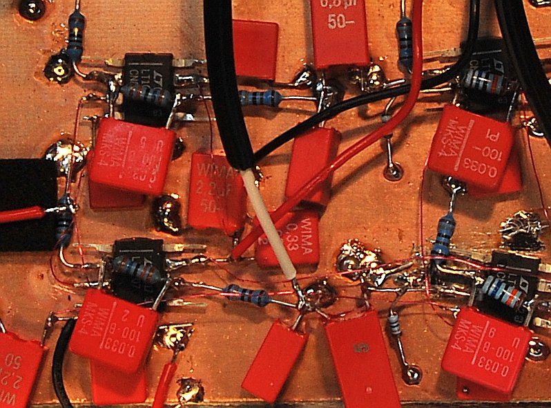
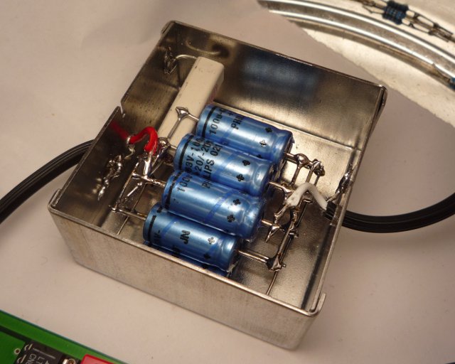
The nMeas-PRE amplifier is very sensitive and needs to reside in a shielded, grounded box.
nMeas-PRE, unfiltered, and the same...
|
... with a Weller WECP-20 turned on
(40 cm distance)
|
nMeas-PRE amplitude response (noise)
The preamplifier is powered by two 9V batteries. It is strongly recommended to keep the
batteries inside the shielded box and twist the cables pairwise.
This will effectively reduce the influence of stray-fields and keep 50/60Hz interferences low.
The input signal first hits the C3/R1 combination, which decouples the DC component of the signal
and additionally creates a high-pass filter (fc ≈ 0.94Hz).
Note: C3 is not a standard capacitor and requires the most attention.
It needs to be selected for extraordinary low leakage current (far down to a two digit nA-value).
See the next chapter for details on that...
The signal is then amplified by a factor of ~10'000 (~80dB, R2/R3) and finally passes
a ~35Hz low-pass filter (R5/C5).
In conjunction with C1, which limits the amplifier 3dB bandwidth to ~34Hz, the amplitude
response drops ~40dB/decade above 30Hz (~50dB drop 10..744Hz; see right; at HP-3582A limit).
Due to dielectric absorption,
it will take hours and hours until the leakage current of the giant input capacitor drops
down to a minimum. If you decided to put the decoupling capacitor C7 inside the box, which is not
recommended, the "sneak-preview-tap" R7/C12, allows for checking the DC component of the
output signal.
Usually, the output will stay at the top rail (~7V) until the input offset drops down below ~700uV.
Disregarding any environmental influences and the 1/f noise contribution of the LT1007
(ultra-low fc ≈ 2Hz), a resistors noise power density can be calculated with:
Or, more common, as voltage noise density:
with
- T = absolute temperature (in K)
- B = bandwith (in Hz)
- k = Boltzmann constant (~1.38e-23 J/K)
Because each noise source is independent of all others, they sum up in a square-sum-root fashion.
At first, we set the input impedance as:
With Av as gain, the output noise voltage density calculates to:
Skipping R2, because its decades above R3 and the resulting sum of R1+R2 won't be much larger than R1:
the output noise estimation becomes
Fortunately, this is not the end of the story. Only considering the above, the four terms would calculate to
(worst case, using maximum voltage and current noise densities at 10Hz):
While the last term (R3 current noise contribution) can be taken out, it is clear to see that
R1 dominates the noise figure. If you manage to find a capacitor >1300uF, with less than
20nA leakage current, decrease R1, but remember to fulfill the high-pass corner frequency requirement
( fc = 1/(2*PI*R1*C3); fc < 0.1Hz).
The lower, the better...
For a detailed description on how to select an apropriate capacitor and why an extremely low leakage
current is mandatory, see the next chapter.
Now, after reducing the formula to
the approximate output voltage noise density (around 10Hz) will be
or 8.3nV/sqrt(Hz), referred to the input.
The left image shows the actual real-world measurement. Marker is at 5Hz and reads ~75uV/sqrt(Hz).
For conversion from Vrms to Vrms/sqrt(Hz), divide the RMS voltage by the square root of the bandwidth
(60mHz, in this case).
Measured performance is a little better than estimated, but indeed, math was done with worst
case LT1007 values taken from the datasheet.
1k3, open input
80dB gain -> ~7.5nV/sqrt(Hz)
HP-3582A, 3mV, 10Hz, 20 avgs, Hann
FIGURE A
|
1k3 with input shorted at C
80dB gain -> ~2.5nV/sqrt(Hz)
HP-3582A, 3mV, 10Hz, 32 avgs, Hann
FIGURE B
|
But that is still not the complete story...
If a voltage source is attached to the input, its output impedance (Rv) appears in parallel to R1,
clamped together via C3.
Notice that the formula above is not true for calculating the noise of the circuit!
The voltage output impedance indeed creates an independent noise-term!
For the ease of it, we assume an ideal voltage source (less math typesetting in LaTeX for me ;-)
The source resistance will now calculate to
with
And all together (except for the latter Xc; my fingers are tired of LaTeX math...)
E.g., at f = 10Hz, we now have a new source impedance of Rs2 ≈ 12Ω.
Although it won't have an influence on the result, the assumption that Rs>>R3 is
not true anymore:
Compared to FIGURE B above, this value is far too large
or 4.5nV/sqrt(Hz).
Why? Evaluating the three terms in the formula above reveals what happened:
At least for this 10Hz approximation, now, the source impedance has almost no influence
on the noise figure. And if we replace the worst case LT1007 settings by more typical
values for the voltage noise density un=2.8nV/sqrt(Hz), we get comparable results:
or 2.8nV/sqrt(Hz), referred to the input.
Instead of calculating the rest by hand, down to 0.1Hz, we simply throw it in the simulator.
Notice that the graph does not show the output voltage noise density, but the portion
of the output noise for the source resistance u(r1) and u(r3) including all contributions
from the LT1007 (most of them unconsidered, in all of the above).
Additionally, with a source impedance as low as ~12Ω, now even R3 (10Ω, 410pV/sqrt(Hz), or
4.1uV/sqrt(Hz) at the output) need to be considered (but its noise is still 1/11 of the LT1007s
contribution).
component noise contribution
referred to output (80dB gain);
shorted C input
|
Here's a direct comparison between
- FIGURE C, Rs = 0Ω (input of LT1007 shorted)
- FIGURE D, Rs = 1k3 || C3
- FIGURE E, same with a finer resolution and logarithmic scale
LT1007 '+' input shorted (Rs=0Ω)
HP-3582A, 3mV, 10Hz, 23 avgs, Hann

FIGURE C
|
1k3 with input shorted at C
HP-3582A, 3mV, 10Hz, 32 avgs, Hann
FIGURE D
|
and the same with a finer
resolution and log scale
FIGURE E
|
Below ~1Hz, the noise of the source impedance noticeably adds to the 1/f noise of the opamp.
While the 1k3-source-impedance version rises above -90dB at ~0.2Hz, the Rs=0Ω-version
is ~6dB lower.
...
nMeas-PRE in a box...

|
this version uses an UniTHAmp
|
Capacitor Selection
2nd stage amplifier (nMeas-AMP)
Sampling Unit (nMeas-???)
|